Soldering LiPo tabs can be challenging because they’re often aluminum or nickel-coated1, which resist solder adhesion. Poor technique can overheat cells, leading to swelling, venting, or internal shorting2 — all dangerous outcomes. Learn the precise cleaning, tinning, and quick soldering3 method to achieve strong, safe joints without damaging your LiPo cells.
To solder LiPo tabs correctly, clean the tab with fine sandpaper or alcohol, apply aluminum or rosin flux, and pre-tin the surface4 using a high-power soldering iron5 (60–80 W) with a broad tip. Work quickly — under 3 seconds — to avoid heating the cell. Then, attach pre-tinned wires using minimal solder and immediate cooling.
I work with LiPo and other lithium chemistries every day in my factory in Shenzhen. I see what goes wrong when people treat tabs like normal copper leads. In this guide, I share the step-by-step process that I actually use so you can avoid killing good packs.
Why Is Direct Soldering to LiPo Tabs Extremely Risky and Generally Discouraged?
Many assume direct soldering saves time, but it exposes the cell’s foil laminate and electrolyte to high temperatures. Excessive heat can cause internal separator melting, electrolyte vaporization, or even thermal runaway6 — permanently damaging the battery. Understand the physics behind LiPo cell design to appreciate why safer alternatives, like spot-welded nickel tabs7, are preferred.
Direct soldering to LiPo tabs is risky because the tabs connect directly to the thin aluminum and copper foils inside the cell. Applying heat longer than 2–3 seconds can cause delamination, electrolyte leakage, or short circuits. Instead, always solder to pre-welded nickel tabs or use a conductive adhesive or spot-welding technique.
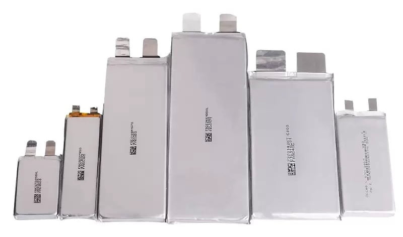
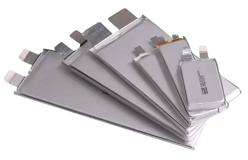
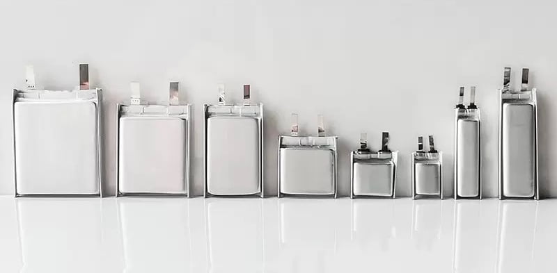
How LiPo Pouch Cells Are Built
Inside a LiPo pouch, there are stacked or rolled layers: positive electrode, separator, negative electrode, and electrolyte. The tab is welded inside the stack. The whole stack works safely only within a narrow voltage and temperature range. A normal LiPo cell works roughly between 3.0 V empty and 4.2 V full.
The tab often uses aluminum on the positive side and copper or nickel on the negative side. These metals are thin. They have low melting points compared to the weld spots inside. When I put a hot soldering iron on the tab for too long, the heat flows along the tab and into the active area. The jelly roll cannot escape that heat.
If that area gets too hot, several things can happen:
- The separator melts or shrinks.
- The electrolyte breaks down.
- Gas forms and the pouch swells.
- Local metal can weld internally and create a micro-short.
A micro-short will not always show right away. The pack may work, but the internal resistance of that cell will rise. The cell will then run hotter in use and age faster.
How Extra Heat and Damage Show Up in Performance
I always think in terms of internal resistance (IR). Every LiPo cell has IR. If I damage a tab or the internal weld, the IR climbs. Higher IR means more voltage drop and more heat at a given current.
I can do a simple calculation. Say I have a 4S pack for an FPV drone:
- Each cell IR when new: 2 mΩ (0.002 Ω)
- Pack IR total: 4 × 0.002 = 0.008 Ω
If the drone draws 80 A at full throttle, power loss inside the pack is:
- P = I^2 x R = 80^2 x 0.008 = 640 x 0.008 = 5.12W
Now I damage one cell tab so its IR doubles to 4 mΩ:
- Pack IR now: 0.002 + 0.004 + 0.002 + 0.002 = 0.010 Ω
- New loss: P = 80^2 x 0.01 = 640 x 0.01 = 6.4W
That extra 1.28 W of heat is inside the pack, near the damaged spot. This seems small, but it is in a very small area with poor cooling. In flight, heat adds over time and pushes the cell closer to thermal runaway.
Why Manufacturers Use Spot Welding Instead of Soldering
Professional cell makers and pack builders almost always use spot welding. Small weld electrodes push onto the tab and a nickel strip. A very high current flows for a few milliseconds. The joint area melts and then cools quickly. The energy stays local, so the cell core stays cool.
A simple table shows how different joining methods compare:
| Method | Heat Time on Tab | Typical Use | Risk to Cell |
|---|---|---|---|
| Spot welding | 3 s | Bad practice | High |
Spot welding uses higher current but much shorter time. The total heat that flows into the cell core stays lower than slow soldering.
Why I Still Sometimes Solder Tabs
I still solder tabs in a few cases:
- I repair a pack where spot welding is not possible.
- I build a prototype for a new drone pack quickly.
- I add a monitor lead or sensor where load is low.
In these cases, I assume the cell will have shorter life. I accept this because the pack is not a final production part.
When I do solder, I use nickel strips between the tab and the wire. I solder the wire to nickel, not directly to the tab. I also keep my contact time short and cool the area between joints.
How Battery Voltage and Damage Risks Relate
I also watch cell voltage when I work. A cell stores more energy and reacts more violently when it stays at high voltage. A typical LiPo cell is full at 4.2 V and empty at 3.0 V. Many pilots land around 3.5 V to extend life.
When I solder, I prefer to work around storage voltage, about 3.7–3.85 V per cell. At this level, the chemical stress inside the cell is lower. If something goes wrong, the reaction is usually less intense.
Energy Stored in a Single Cell
I like to think in watt-hours. A 4.2 V, 1500 mAh cell stores:
- Capacity: 1500 mAh = 1.5 Ah
- Energy: E = V x Ah = 4.2 x 1.5 = 6.3Wh
When I solder on a 4S pack, I might have four times that, about 25.2 Wh in one small brick. This is enough energy to melt plastic and start a fire if released quickly. This is why I treat tab soldering as a last resort. The risk is real and always present.
What Tools and Safety Equipment Are Mandatory When Soldering LiPo Battery Tabs?
Many DIY or lab setups skip essential safety gear when handling high-energy LiPo cells8. A single spark, short, or overheat can result in venting, toxic fumes, or even fire. Having the correct tools and protective equipment ensures precision, repeatability, and safety for operators.
Mandatory tools include a 60–100 W temperature-controlled soldering iron with a wide chisel tip, aluminum or rosin flux, 60/40 solder, and a heat-resistant surface. Safety gear must include heat-resistant gloves, safety goggles, fume extraction, and a LiPo-safe container or sand bucket for emergencies. Always keep a Class D fire extinguisher nearby.
Core Soldering Tools I Use
I start with a proper soldering station9. I avoid small pencil irons with fixed low power. They cannot dump enough heat into the joint quickly. I prefer:
- Power: 60–100 W station.
- Temperature control: digital, stable.
- Tips: wide chisel or hoof tip with good thermal mass.
For solder, I usually use leaded 60/40 or 63/37 with rosin core in the factory. Melting temperature is lower than many lead-free alloys, so I get shorter dwell time. In regions where leaded solder is not allowed, I use a high-quality lead-free alloy with extra flux and slightly higher temperature.
Here is a simple table:
| Solder Type | Composition | Melt Range (°C) | Notes |
|---|---|---|---|
| Sn60/Pb40 | 60/40 | 183–190 | Good wetting, common in labs |
| Sn63/Pb37 (eut.) | 63/37 | 183 (single) | Sharp melt, very nice to work |
| SAC305 | Sn96.5/Ag3/Cu0.5 | 217–220 | Lead-free, needs higher temp |
I always pair the solder with an extra flux pen10. I use no-clean or rosin flux made for electronics. I avoid acid flux because it will attack the metals and cause corrosion over time.
Holding and Protection Tools
I never hold the pack in my hand while I solder. I put the cell or pack into a non-metallic jig. Wood or high-temperature plastic works well. I use:
- A wooden block with slots for the pouch body.
- 3D printed brackets that grip the sides of the pack.
- Non-metallic clamps to hold the nickel strip.
I also use Kapton tape and sometimes fiberglass tape. I tape down all unused tabs and cover exposed metal. This stops accidental shorts when the tip or wire slips.
Safety Gear I Consider Non-Optional
LiPo packs can burn fast. A burning pouch will produce flame and toxic smoke. I respect that risk. I always set up:
- Safety glasses. I protect my eyes from hot solder and fragments.
- Fume extraction or at least a fan that pulls fumes away from my face.
- A ceramic tile or thick metal tray under the work area.
- A bucket with dry sand, or a metal box, to drop a burning pack inside.
- A Class D or lithium-rated extinguisher if possible. If not, at least a normal ABC extinguisher to fight surrounding fires.
I do not trust cheap “LiPo bags” alone. Tests show that many fabric bags cannot fully contain a large LiPo fire. They are better than nothing, but I still prefer a metal box or sand.
Why a Strong Iron Means Less Risk, Not More
Many people fear a 100 W iron near a LiPo. I understand that feeling. The key truth is that a strong iron with good control lets me work faster. A weak iron forces me to sit on the tab for a long time while the joint slowly warms up. The cell core gets a long heat soak.
With a strong iron and a big tip, I touch the joint, melt within one or two seconds, and pull away. The tab heats locally and then cools. The heat does not travel as far into the cell.
I can think of it like this: total heat = power × time. If I double power but cut time to one quarter, total energy is half.
Example:
- Small iron: 30 W × 8 s = 240 J.
- Big iron: 80 W × 2 s = 160 J.
The big iron with short contact actually delivers less total energy into the joint.
Simple Pack Rating Check Before I Start
I also think about the pack rating before I work. If I solder tabs on a high-current FPV pack, I must keep joints very low in resistance. A typical drone pack might be:
- 6S 1300 mAh.
- C rating: 75 C (effective maybe 40 C in real use).
Theoretical current:
- I_{max} = 1.3Ah x 75 = 97.5A
If my tab solder joint adds just 0.5 mΩ (0.0005 Ω) extra, then at 100 A:
- P = I^2 x R = 100^2 x 0.0005 = 10,000 x 0.0005 = 5W
So that small extra resistance will dump 5 W of heat into the joint at full throttle. This is why my tools and joint quality matter so much.
Personal Routine Before I Solder Any Tabs
My own routine is simple:
- I clear the bench and remove flammable items.
- I place a ceramic tile and metal tray.
- I set up the cell in a jig at storage voltage.
- I tape down all exposed leads.
- I set iron temperature and select the large tip.
- I test on a scrap nickel strip first.
Only when all of this is ready do I bring the pack onto the bench. This slow setup actually reduces total job time because I rarely stop to fix mistakes.
How Do You Properly Tin Nickel Strips and LiPo Tabs Before Joining Them?
Improper tinning causes cold joints11 and weak electrical connections. A poor bond increases resistance, generates heat under load, and reduces battery life. Tinning both surfaces correctly ensures strong, low-resistance joints that last through cycles.
To tin nickel strips or LiPo tabs, clean the surface with alcohol and lightly sand it. Apply flux, then quickly touch the soldering iron to the tab and apply a small amount of solder until it flows evenly. Let it cool. Do the same for the wire or strip before joining them.
Why Pre-Tinning Is So Important
When two dry metal surfaces touch, solder must wet both sides and fill the gap at the same time. This takes longer. Pre-tinning gives me a solder layer on both parts. When I join them, I only need to melt these thin layers and merge them. This is much faster.
Think of it as building two small “solder pads” first. Then I only “glue” the pads together.
Step-by-Step Tinning Process
I follow a fixed sequence:
-
Prepare the nickel strip.
I cut the strip to size. I use fine sandpaper or a fiberglass pen to lightly scuff the area where I will solder. I wipe off dust. -
Apply flux.
I use a flux pen to wet the area. I do not flood it; a thin film is enough. -
Pre-heat the iron tip.
I make sure the tip is clean and well tinned. I set the temperature to around 350–380 °C for leaded solder or 380–420 °C for lead-free, depending on the iron. -
Tin the nickel strip.
I touch the iron and feed a small amount of solder. I drag the solder across the area to make a thin shiny film. Contact time is usually 1–2 seconds. -
Prepare the tab.
I gently clean the tab with isopropyl alcohol. I do not sand hard near the base because the metal is thin. A light scuff is okay on the outer part. -
Flux the tab.
I add a thin layer of flux. -
Tin the tab quickly.
I support the tab with a small block close to the pouch. I then touch the iron with a small ball of solder and count “one, two” in my head. I pull away as soon as the solder wets the surface.
The goal is a smooth, thin layer, not a big blob.
How Much Solder Is Enough?
I do not want a heavy dome of solder on the tab. A thick blob adds weight and makes the joint stiff. A stiff joint will bend at the base of the tab and can tear it later.
I aim for a thin layer that just hides the raw metal. When I press the tinned nickel onto the tab later, these two layers will melt and merge. That will add a little more volume, but still stays flat.
Here is an Simple Example: Joint Area and Current Density
I like to estimate current density12 to think about how large the soldered area should be. Say I have a 6S FPV pack that may pull 80 A. I solder a nickel strip that is 8 mm wide and I cover 6 mm of length on the tab.
- Area(A) = 8mm x 6 mm = 48 mm^2 = 0.48 cm^2
Current density J at 80 A:
- J = I / A = 80 / 0.48 ~ 167 A/cm^2
If I only solder a 4 mm × 4 mm patch (16 mm² = 0.16 cm²):
- J = 80 / 0.16 = 500 A/cm^2
Higher current density means higher local heating. So I always try to cover a reasonable area of the tab without going too close to the pouch edge.
Tinning Wires and Leads
I also pre-tin the wire that will connect to the nickel. I strip the insulation, twist the strands, apply flux, and then feed solder until the strands are fully soaked. I avoid huge blobs on the wire because they also add stiffness.
When I later solder the wire to the nickel strip, I again only need to reflow two tinned surfaces.
Common Tinning Mistakes I Avoid
I see the same mistakes often:
- People keep the iron on the tab for 5–10 seconds.
- People let the solder sit dull and grainy, which means poor wetting.
- People use acid flux13, which eats the joint over time.
- People do not support the tab and bend it at the base while tinning.
I avoid all of these by planning the motion before I touch the iron. I also rehearse the move a few times in the air to build muscle memory.
Visual Checks After Tinning
After tinning, I always check:
- The solder layer14 looks smooth and shiny.
- No burnt flux or dark spots.
- No melted insulation nearby.
- The tab still feels flexible and shows no discoloration at the base.
If the tab turns blue or brown near the pouch, it often means I overheated it. In that case I am more cautious with that cell in later tests.
What Soldering Iron Temperature and Tip Size Prevent Overheating LiPo Tabs?
Incorrect soldering temperatures15 can either fail to melt solder or overheat the tab. Overheating degrades the separator film inside LiPo cells, while too little heat causes incomplete bonding. Control temperature and contact time to achieve efficient heat transfer without damage.
Use a 60–100 W soldering iron16 set between 350–400 °C with a broad chisel or hoof tip for maximum heat transfer. The wide tip delivers quick heat, minimizing dwell time. Touch the tab for no longer than 2–3 seconds, then remove immediately and cool with compressed air or a metal clip.
How Temperature, Time, and Tip Size Work Together
Heat transfer depends on three main factors:
- Tip temperature.
- Contact time.
- Tip contact area and thermal mass17.
If temperature is too low or the tip is too small, solder never fully wets the surfaces. The operator keeps the iron on the joint longer, and that long exposure drives heat into the pouch. If temperature is too high or contact is too long, the tab can discolor and the separator inside can get damaged.
So I do not focus on temperature alone. I think of the full triangle: right temperature, big enough tip, and very short contact time.
Typical Temperature and Dwell Time Ranges
This simple table shows what I aim for:
| Solder Type | Iron Temp (°C) | Tip Size | Target Dwell on Tab |
|---|---|---|---|
| Leaded | 350–380 | 3–5 mm chisel | 1–2 s |
| Lead-free | 380–420 | 3–5 mm chisel | 1–2 s |
I still adjust based on my iron and the tab size. If I see that solder takes longer than 2 seconds to fully melt, I may slightly raise the temperature or use a larger tip.
Simple Energy Comparison Example
I like to compare two cases to show why higher temperature plus shorter time can be safer.
Case A:
- Temperature: 320 °C.
- Power: 40 W.
- Contact time: 6 s.
Approximate energy:
- E_A = 40 x 6 = 240J.
Case B:
- Temperature: 380 °C.
- Power: 80 W.
- Contact time: 2 s.
Approximate energy:
- E_B = 80 x 2 = 160J.
Even though the tip in Case B is hotter and more powerful, the total energy dumped into the joint is lower. The cell core sees less heat over time, which is what matters for damage.
Why Tip Shape Matters
A large chisel or hoof tip gives me:
- A wide contact area with the tab and nickel.
- Good stored heat, so the temperature does not drop much when I touch the joint.
- Better control of solder flow.
Pointy tips do not work well on tabs. They have low thermal mass and tiny contact area, so they cool quickly when they touch the metal. The operator then holds them longer on the joint, which again sends more heat into the cell.
Monitoring Tab and Cell Temperature
I also monitor temperature directly when possible. I sometimes use:
- A contact thermometer with a small probe near the base of the tab.
- An infrared thermometer aimed at the tab area.
- My fingertip after a short cool-down. If I cannot hold my finger on the tab after a few seconds, it was too hot.
I try to keep the tab area under roughly 60 °C during work. Above that, the risk of internal damage rises. Typical LiPo cells have recommended operating ranges up to around 60 °C. Frequent overheating will age them fast.
In one project, we built a small batch of 6S packs for an FPV customer. A junior technician used a weak iron at 320 °C with a tiny tip. He held the iron for 5–6 seconds on each tab. The packs worked at first but later showed:
- Elevated internal resistance on two cells.
- Faster voltage sag at high throttle.
- Hot spots near the tab area.
We reworked the process with a 90 W station at 380 °C and a wide chisel tip. Dwell time dropped to 2 seconds. New packs had lower IR and stayed cooler in flight. The difference was clear in both numbers and pilot feedback.
How Do You Clamp or Hold LiPo Cells Securely While Soldering Tabs Without Shorting?
Handling live LiPo cells can be tricky — one slip can cause a short or puncture. A momentary short across terminals can cause sparks or cell failure. Secure the cells with proper insulation and mechanical stability18 during soldering.
Use a non-conductive clamp19, such as a 3D-printed holder or wooden jig, to keep the cell stable. Always insulate exposed terminals with Kapton tape20 or heat-resistant silicone pads. Ground yourself to prevent static discharge. Avoid using metal clamps, and keep a small gap between positive and negative tabs.
Why Mechanical Stability Matters So Much
A LiPo pack has low internal resistance. A short between main positive and negative can cause hundreds of amps to flow for a brief moment. A clamp that slips or a wire that whips into another tab can create this short in an instant.
I want both hands free for iron and solder. A good jig lets me do that. I do not rely on my other hand to hold the pack.
Simple Jig Options I Use
I have used several simple jigs that work well:
-
Wooden block jig.
I cut a pocket in a wooden block that matches the pack size. The pack sits snugly. I add small wooden “fingers” that hold down the pouch edges with screws or clamps. -
3D printed frame.
I design a U-shaped frame that hugs the sides of the pack. The top opening leaves room for the tabs. I add small printed arms with holes for bolts or non-metal screws to pin down the tabs. -
Non-metal vise.
Some electronics vises use nylon or plastic jaws. I clamp the pack gently by the sides, not by the faces, so I do not crush it.
In all cases, the material touching the pack is non-conductive and heat resistant enough for short work.
How I Prevent Shorts While Clamping
I identify all conductors:
- Main positive tab.
- Main negative tab.
- Balance tabs (if I have a multi-cell pouch).
- Any exposed nickel strips.
Then I:
- Cover unused tabs with Kapton tape.
- Place foam or cardboard between tabs if they are close.
- Route wires away from the joint area and tape them down.
If I need to clamp near the tabs, I use plastic clips, not metal ones. I never let metal clamps touch bare tabs or nickel. If I must use a metal tool near a live tab, I cover it with heat shrink or tape.
Balance Leads and Multi-Cell Packs
If I work on a multi-cell pouch with several tabs, things get more complex. The balance tabs carry intermediate voltages. A short from a high-potential tab to a lower one can over-discharge part of the stack and damage that section.
I label each tab and I am careful to:
- Only expose the tab I am working on.
- Tape or fold back the others.
- Never let the iron or solder bridge between tabs.
A simple drawing on paper that maps tab positions to cell numbers helps. I keep it near the jig so I do not lose track.
Here is an Example: Jig Layout for a 4S Flat Pack.
For a flat 4S pack, I might have:
- Positive main tab at one corner.
- Negative main tab at the opposite side.
- Balance tabs in between.
I design the jig so:
- The pack lays flat with tabs pointing out.
- A raised ridge sits between positive and negative main tabs.
- Each balance tab has a small slot where it can bend up individually.
This way, even if a tab springs back, it will hit a ridge or wall, not another tab.
Mechanical Support to Avoid Tab Tear
The clamp must also support the base of the tab. If the tab floats in the air and I push on it with the iron or wire, the bending moment concentrates at the weld inside the pouch. Over time, this can weaken or tear the internal connection.
I like to place a small block or piece of FR-4 under the tab near the base. I tape the tab to this support with Kapton. When I press during soldering, the load spreads along the tab instead of pulling at the weld.
What Is the Fastest Safe Technique to Solder Tabs in Under 2–3 Seconds?
Lingering with a soldering iron can destroy a LiPo cell internally. The longer the heat, the greater the risk of delamination and short circuits. Master a rapid soldering technique combining preparation, precision, and timing.
Pre-tin both tab and wire separately, then align them firmly before soldering. Touch the iron to both surfaces simultaneously, feed a small bit of solder, and remove the iron within 2 seconds. Immediately cool the joint using compressed air or a metal heat sink. Practice on scrap tabs to refine timing.
Breaking the Job into Clear Stages
I divide the process:
- Tinning stage: I tin all parts separately.
- Positioning stage: I clamp and align everything without heat.
- Joining stage: I reflow in one quick touch.
By the time I bring the iron to the joint, there is nothing left to adjust. My only job is to melt and pull away.
The One-Shot Reflow Routine
My actual sequence for the joint is:
- I apply fresh flux on both tinned surfaces.
- I press the tinned nickel strip onto the tinned tab using a small non-metal tool or clamp.
- I load a tiny amount of solder on the iron tip.
- I touch the tip to the edge of the joint, not the middle, so solder flows through the interface.
- I watch for the solder to go fully shiny across the entire contact area.
- I count “one, two,” then I lift the iron straight up.
- I hold the parts still for a few seconds while the solder freezes.
This “touch, melt, hold, remove” rhythm keeps the contact time very short.
Practice on Scrap First
I always tell my team to practice on scrap before they touch real cells. I give them:
- Loose nickel strips.
- A dummy aluminum strip.
- The same wire gauge and solder.
They practice the one-shot reflow repeatedly until they can create smooth joints in one or two seconds. This way, when they work on a real tab, they already have the motion in muscle memory.
Simple Timing Check
If I want to be sure about my timing, I sometimes record a video on my phone. I then count frames. Most phones record at 30 frames per second. If my contact time shows as 45–60 frames, I know I stayed on the joint for 1.5–2 seconds.
If I see 90 or more frames of contact (3 seconds or more), I know I need to adjust technique or increase tip size21 or temperature.
Here is an Example: Power Joint for a High-Current Pack
Assume I build a 4S 1500 mAh FPV pack that might see peaks of 100 A. I want a strong joint at each main tab. With good pre-tinning and one-shot reflow, I can create:
- A flat, wide soldered area.
- A smooth fillet at the nickel edges.
- No burned flux or dark joints.
After the joint cools, I check mechanical strength by pulling the nickel strip sideways and up. The tab should bend before the solder joint fails. A weak joint will peel off or crack easily.
Thermal Impact of Fast Vs Slow Technique
If I compare two operators:
- Operator A uses slow technique with 5 seconds of dwell.
- Operator B uses one-shot reflow with 2 seconds of dwell.
If both use 80 W irons, then:
- Operator A energy: 80 x 5 = 400J.
- Operator B energy: 80 x 2 = 160J.
Operator B sends less than half the energy into the joint. This is why I care about technique as much as I care about iron settings.
How Do You Avoid Common Mistakes That Cause Tab Tears or Internal Damage?
Many solder joints fail because of mechanical stress, not just heat. Repeated bending or excessive pulling tears the fragile foil tab, compromising the cell seal. Handle tabs delicately and use strain relief22s to protect connections.
Avoid excessive bending of tabs. Support them with tweezers or a clamp while soldering, and never twist the tab. Use flexible silicone wire and secure it with hot glue or Kapton tape for strain relief. Always allow the solder joint to cool completely before any movement or repositioning.
Typical Mistakes I See
Some frequent issues:
- Big solder blobs23 that make the joint stiff.
- Wires routed straight up and bent sharply 90° at the tab base.
- Tabs twisted back and forth during pack assembly.
- Wires pulled while disconnecting the pack, using the joints as a handle.
All of these stress the thin metal where it enters the pouch.
Keeping Joints Low and Flat
I aim for low, flat joints along the tab plane. I avoid stacking the wire directly on top of the tab. Instead, I often:
- Lay the wire along the tab lengthwise.
- Solder it in a “lap joint” style with the strands spread a bit.
- Cover the joint with tape to keep it from flexing away from the tab.
This reduces bending leverage at the base.
Strain Relief Techniques
After soldering, I always add strain relief. Some simple methods:
- I tape the wire to the pouch a few centimeters away from the tab, so any pull happens between tape and plug, not at the tab.
- I use heat shrink over the joint and some of the wire, then tape that to the pack.
- In bigger packs, I add a small 3D printed cable guide that clamps onto the pack without touching the tabs.
The idea is to move the “flex point” away from the fragile tab-pouch area.
Here is an Example: Estimating Bending Stress
Think of the joint as a lever. If a 10 N force (about 1 kg pull) is applied at the end of a 40 mm wire before the first tape point, the bending moment at the base is:
- M = F x L = 10 x 0.04 = 0.4N·m.
If I add strain relief only 20 mm from the tab, the same pull gives:
- M = 10 x 0.02 = 0.2N·m.
So the bending load at the tab base halves. Over many cycles, that can make the difference between a long-lasting pack and an early failure.
Avoiding Overheating and Thermal Cycling
Internal damage also comes from repeated thermal stress. If a tab joint runs hot in use due to high resistance, the tab and internal weld expand and contract more than the surrounding pouch material. Over time, this can cause micro-cracks.
To reduce this, I:
- Keep joint resistance very low with good technique.
- Avoid packing cells so tightly that the tab area cannot cool.
- Design the pack layout so that airflow from the drone or device reaches the tab area if possible.
When I see brown discoloration or hardened plastic near the joints after some cycles, it is a sign that the area is running too hot.
Mechanical Handling Rules in the Workshop
In my workshop, I enforce small rules:
- People must never carry packs by their wires.
- People must not twist tabs to “align them better” after they are welded.
- People must support tabs before any rework.
- People must not scrape aggressively on tabs to clean them; they should use gentle methods.
These small rules prevent many silent failures.
When Should You Choose Spot Welding Over Soldering for LiPo Tab Connections?
Soldering isn’t ideal for every LiPo application, especially in high-energy packs. Manual soldering limits scalability, consistency, and safety in production. Know when to use industrial spot welding for efficiency and long-term reliability.
Spot welding is preferred over soldering when assembling multi-cell Li-ion or LiPo packs, especially for EVs, drones, and medical devices. It uses brief electrical pulses to fuse nickel tabs to cells without heating the electrolyte. Choose spot welding for high-volume or mission-critical applications requiring consistent, low-resistance joints.
How Spot Welding Works and Why It Is Gentler on Cells
Spot welding uses two copper electrodes that press onto the tab and nickel strip. A short, high-current pulse flows and melts a small region between them. The melted metal then solidifies into a weld nugget.
The benefits:
- Heat stays mostly in the joint area.
- The pulse is only a few milliseconds.
- The cell core sees very little temperature rise.
This is very different from holding a soldering iron on the tab for seconds.
Comparing Joint Resistance
Both solder joints and spot welds can achieve low resistance if made well. But spot welding avoids added solder alloy and keeps the current path in the base metals and nickel.
If one spot weld has resistance of 0.05 mΩ and I make four welds per joint, the total joint resistance24 might be 0.2 mΩ. A soldered joint might be similar, but the process has more variability between operators.
At 80 A:
- Spot weld loss: P = 80^2 x 0.0002 = 6400 x 0.0002 = 1.28W.
- A sloppy solder joint at 0.5 mΩ: P = 6400 x 0.0005 = 3.2W.
So a poor solder joint can add more than double the heat at the same current.
Application-Based Decision Table
I use a simple mental table:
| Application | Current Level | Volume | My Choice |
|---|---|---|---|
| FPV drone packs (4S–6S, 60–120 A) | High | Medium | Spot welding |
| EV scooter / bike packs | High | High | Spot welding |
| Small IoT or low-current packs | Low | Low | Solder ok |
| Prototyping new pack layout | Varies | Very low | Often solder |
| Repair of a single tab | Varies | Very low | Solder (care) |
If a customer like a drone manufacturer orders thousands of packs, I never rely on hand soldered tabs. The long-term safety and brand risk is too high.
Cycle Life and Cost Considerations
Spot welded packs almost always show better cycle life. Cells keep lower internal resistance longer. Over hundreds of cycles, the difference in performance and heat is clear.
Yes, a good spot welder and fixtures cost money. But for a company shipping packs to end users, this cost is small compared to:
- Warranty returns from failed packs.
- Potential damage to drones or devices.
- Safety reputation and compliance.
For a hobbyist building one or two packs, soldering may be acceptable with care. For a business, I treat spot welding as the standard.
Here is an Example: Calculating Energy Loss Over a Flight
If a 6S FPV pack delivers 80 A for a 3-minute flight (0.05 h) and the joint resistance is 0.2 mΩ per connection with spot welding:
- Loss power per joint: 1.28 W.
- For two main joints (positive and negative): 2.56 W.
- Energy lost in joints: E = P x t = 2.56 x 0.05 = 0.128Wh.
With a poor solder joint at 0.5 mΩ per connection:
- Loss power per joint: 3.2 W.
- For two joints: 6.4 W.
- Energy lost: 6.4 x 0.05 = 0.32Wh.
The difference per flight seems small, but that extra heat is concentrated in the joints and tab bases, and it repeats every flight. Over 200 cycles, that is 40–60 Wh of extra heat, which ages the pack and increases risk.
Regulatory and Quality Aspects
Many industries have strict safety and reliability standards. For medical devices, EVs, and industrial equipment, auditors often expect spot welding or equivalent automated joining processes25. Hand soldering on tabs can be seen as a red flag.
In my factory, any pack that goes into a certified product must use documented, controlled welding processes. Soldering appears only in repair procedures, not in the main line.
Conclusion
In this guide, I showed why LiPo tab soldering is risky, which tools and temperatures I use, how I clamp cells, and why fast one-shot joints matter. I also explained when spot welding is the smarter choice. If you want help designing safer custom packs or OEM battery solutions, you can always reach me at ViBMS for professional support.
-
Learn about the materials used in LiPo tabs and their impact on soldering. ↩
-
Explore the factors leading to internal short circuits in LiPo cells. ↩
-
Discover efficient methods for preparing and soldering LiPo tabs. ↩
-
Learn why pre-tinning is crucial for strong solder joints. ↩
-
Find out the best soldering iron specifications for working with LiPo batteries. ↩
-
Understand the dangers of thermal runaway and how to prevent it. ↩
-
Discover the advantages of using spot-welded tabs for LiPo batteries. ↩
-
Learn about the potential hazards of handling high-energy LiPo batteries. ↩
-
Find out what to look for in a soldering station for LiPo battery work. ↩
-
Understand how a flux pen enhances soldering quality and efficiency. ↩
-
Learn about cold joints and their impact on electrical connections. ↩
-
Explore the relationship between current density and solder joint performance. ↩
-
Learn why acid flux can damage solder joints over time and discover safer alternatives. ↩
-
This resource provides tips on achieving the perfect solder layer for reliable connections. ↩
-
Find out the optimal soldering temperatures to prevent damage to LiPo cells during soldering. ↩
-
Explore this link to find the ideal soldering iron that ensures efficient heat transfer and prevents overheating. ↩
-
Explore the concept of thermal mass and its impact on soldering efficiency and safety. ↩
-
Learn how mechanical stability can prevent shorts and ensure safe soldering practices. ↩
-
Find recommendations for non-conductive clamps that enhance safety during soldering. ↩
-
Discover the benefits of using Kapton tape for insulation and protection in soldering. ↩
-
Understanding tip size can enhance your soldering technique and improve joint quality. ↩
-
Explore various strain relief methods to protect soldered connections from mechanical stress. ↩
-
Learn about the impact of solder blobs on joint quality and how to avoid them. ↩
-
Discover how joint resistance impacts battery efficiency and longevity, crucial for high-performance applications. ↩
-
Discover the role of automated joining processes in enhancing the quality and reliability of battery manufacturing. ↩